Museum News 2004

(Back to Archive News Page)

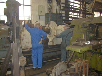
May 2004.

Reliant Paddle Tug, Side-Lever Engine - If you you remember the crankshaft came to us in two pieces, (see MUSEUM NEWS 2002) these have now been reunited. They were transported to Sam Ward's workshop in Kilamarsh, South Yorkshire where the oxy-acetylene burnt ends were machined square and a male and female spigot produced in the lathe. The two shafts were then forced together using a hydraulic press, rigged up in the lathe. At the joint a deep chamfer had been machined on both halves to produce a vee groove, which was filled by a continuous weld as the lathe slowly revolved. When finished the top of the weld was machined level to the original shaft diameter, which produced an almost invisible and extremely strong joint. The shaft is now back at the museum.

Paddle wheel hub and shaft in the lathe Removing the paddle wheel hub and shaft from the lathe. Note the new machined left hand end.
Repaired hub and crankshaft 
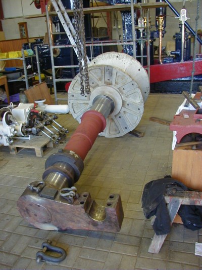
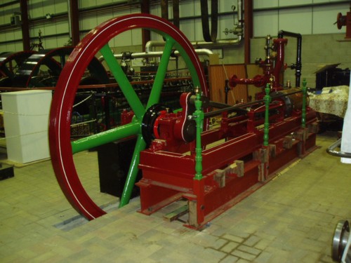
The repaired paddle wheel hub and crankshaft back at the museum.
(Photos - Paul Bond)

Only one half of the slip eccentric has survived. A fabricated replacement for the missing half has been made 'in house' and is, at this moment, being machined in the museum workshop.

It is intended to have the paddle wheel, and its paddle feathering gear, operating alongside the engine. A large fabricated structure is now in place (to substitute the side of the tug), which will support the paddle shaft bearing.


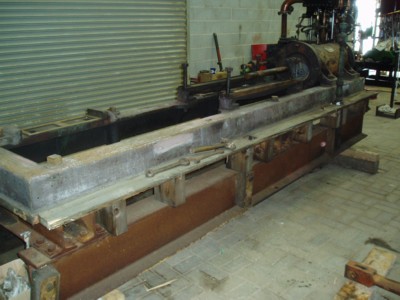
Yarwood Vertical Compound Marine Engine No. 193 (Out of the dredger 'SEIONT II).
Steady progress has been made on this engine. The big end and main bearings have been dismantled to reveal some corrosion and scoring of the journals. These have been cleaned up and re-assembled with shim adjustment etc. for correct running clearances.
Most of the old paint has been removed and the engine repainted a light grey, which is the same colour when it came out of service.

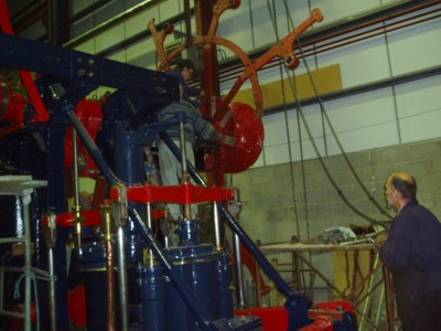
The Yarwood compound marine engine just as it was after unloading. Yarwood Marine Engine

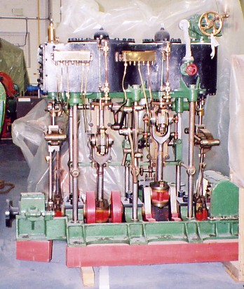
Samuel White Vertical Marine Compound Engine No.1239
This engine has now been completely rebuilt, except for the air pump. Just before Christmas last year it was oiled up and thoroughly warmed through. But when we opened the steam valve it would only move about half a rev. and then stop. At the same time the reversing lever locked up and would only become free when the steam was shut off and the pressure dropped. After trying several ways to overcome the problems the conclusion seemed to point to the HP piston valve.
With the piston valve removed and dismantled the only obvious fault was that the piston ring gaps looked excessive, which would cause abnormal steam leakage. The steam within the gaps could also force the rings outwards onto the valve cylinder wall causing the reversing lever to lock up (apparently a common fault!). Brass inserts were made and fitted to reduce the gaps to around 0.015ins. (difficult to mearsure in situ).

We also took the opportunity to check the valve port openings and the amount of lead on both the HP and LP steam cylinders ie. the amount the steam port is open when the piston is on top and bottom dead centre. On marine engines it is common practice to have more lead on bottom dead centre that on top dead centre. This is to allow for the weight of conrods and pistons etc. to be lifted against gravity.
The checks revealed that some of the setting were in fact just the opposite and so adjustments were made by inserting and removing packing pieces between the relevant eccentric and rods.

Early in February the engine was again tried on steam. Thankfully this time it started straight away and ran quite well - slightly smoother in 'forward' than in 'astern'.
There are still one or two minor jobs still to do but for now it will be run regularly on our steaming days.

Samuel White marine engine, after restoration 
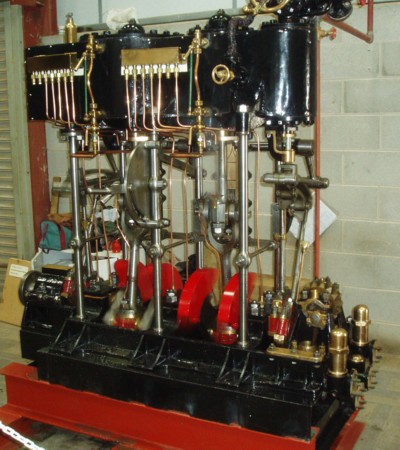
Samuel White vertical compound marine engine after restoration.
Samuel White marine engine, before restoration 
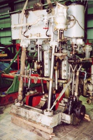
Samuel White vertical compound marine engine before work started on it.

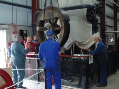
Fleming & Ferguson Marine Engine.

This engine has always run a little bit uneven, particularly at slow revs. It was recently decided to replace the existing flywheel with one of a larger mass and a balance weight to counter the 'out of balance forces' of the engine.
To do this two flywheels were fastened together. The balancing weight was achieved by casting molten lead between two of the spokes and by attaching rolled steel plates around halve of the circumference of the flywheel rims (see photo).
The whole assembly was fitted to the engine shaft using a taper hub so that the correct position could be adjusted and then locked in place.
The modifications to the flywheel etc. was done at Sam Ward's workshop.
The gap left on the flywheel rim was filled in by bending and glueing together thin sheets of MDF board, and now it is painted it looks just the same as any other flywheel.
The engine now runs quite smoothly.

Hoisting the flywheel into place The modified flywheel being lowered into place. The balancing weights can be seen quite clearly.

June 2004.

Monday 21st June saw the arrival of another engine at the museum - A horizontal, single cylinder, slide valve engine, and four bar cross-head guides.
Cylinder diameter 12ins. Stroke 24ins. and a flywheel diameter of 8ft.
It was built for the Barnsley Brewery Co. in 1874 by Needham, Qualter, Hall & Co. at Railway Foundry, Barnsley.
The engine has been stripped down cleaned and checked for wear/damage and was found to be in remarkably good mechanical condition. Because of its simple design it wasn't long before it had all been re-assembled. A flywheel pit and concrete pillar, to support the outer flywheel bearing, had to be constructed before it could be moved to its present position.
With a temporary steam supply and exhaust fitted it was steamed for the first time, for many a year, on Wednesday 20th October 2004. The engine looks well after having a new coat of paint and line work. With permanent plumbing now in place it is run regulary on steaming days.

QH Engine - Bed. Stripped down to the cylinder and bed castings.
QH Engine - Slide valve cover removed The slide valve with cover removed.
The finished engine. QH Engine - Finished


Reliant Paddle Tug, Side-Lever Engine
The two crankshaft bearings on the engine and the outer paddle shaft bearing, have all been lined up with each other. This was a tricky operation using a taught wire held along the axis of the bearings.
The fabricated support column for the outer bearing was then secured to the concrete foundation.
The paddle wheel hub, crankshaft and crank were then lifted into the bearings, as was the short splined shaft, which carries a slip eccentric to operate the valve gear. The disengaging mechanism, which slides on the splines, has been fitted and checked for free movement.

The existing paddle wheel arms and rims were separated from the hub some time before they arrived at the museum. Their relative positions to each other were not recorded, therefore one or two trial assemblies of all parts will have to be made before an acceptable fit can be arrived at. After that a new set of arms (mirror image of the existing arms) will have to fabricated and individually fitted to complete the wheel framework before the paddles can be fitted.

Fitting paddle wheel frame Trial fitting of parts of the paddle wheel frame to the hub.

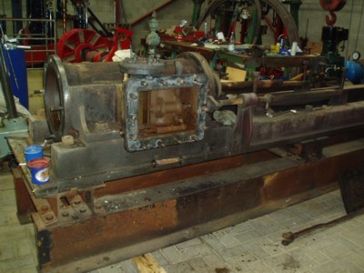
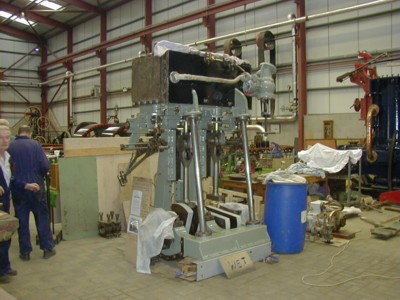
Yarwood Vertical Compound Marine Engine No. 193

Progress Report:

After a bit of research and head scratching it was found, that at some time prior to the engine arriving at the museum, the eccentic rods had been crossed over. They have now been fitted to their correct eccentrics.
The air pump has been fitted and its linkage connected to the HP cross-head etc.
Nearly all the lubricating pipes and drains are now back in their relative positions.
Its first trial steaming day is getting closer!

Yarwood vertical compound engine The Yarwood Vertical Compound Engine under restoration.

Top of Page